| Internet-Draft | Set Union | August 2022 |
| Summermatter & Grothoff | Expires 5 February 2023 | [Page] |
This document contains a protocol specification for Byzantine fault-tolerant Set Reconciliation.
This Internet-Draft is submitted in full conformance with the provisions of BCP 78 and BCP 79.
Internet-Drafts are working documents of the Internet Engineering Task Force (IETF). Note that other groups may also distribute working documents as Internet-Drafts. The list of current Internet-Drafts is at https://datatracker.ietf.org/drafts/current/.
Internet-Drafts are draft documents valid for a maximum of six months and may be updated, replaced, or obsoleted by other documents at any time. It is inappropriate to use Internet-Drafts as reference material or to cite them other than as "work in progress."
This Internet-Draft will expire on 5 February 2023.
Copyright (c) 2022 IETF Trust and the persons identified as the document authors. All rights reserved.
This document is subject to BCP 78 and the IETF Trust's Legal Provisions Relating to IETF Documents (https://trustee.ietf.org/license-info) in effect on the date of publication of this document. Please review these documents carefully, as they describe your rights and restrictions with respect to this document. Code Components extracted from this document must include Revised BSD License text as described in Section 4.e of the Trust Legal Provisions and are provided without warranty as described in the Revised BSD License.
This document describes a byzantine fault tolerant set reconciliation protocol used to efficient and securely compute the union of two sets across a network.
This byzantine fault tolerant set reconciliation protocol can be used in a variety of applications. Our primary envisioned application domain is the distribution of revocation messages in the GNU Name System (GNS) [GNS]. In GNS, key revocation messages are usually flooded across the peer-to-peer overlay network to all connected peers whenever a key is revoked. However, as peers may be offline or the network might have been partitioned, there is a need to reconcile revocation lists whenever network partitions are healed or peers go online. The GNU Name System uses the protocol described in this specification to efficiently distribute revocation messages whenever network partitions are healed. Another application domain for the protocol described in this specification are Byzantine fault-tolerant bulletin boards, like those required in some secure multiparty computations. A well-known example for secure multiparty computations are various E-voting protocols [CryptographicallySecureVoting] which use a bulletin board to share the votes and intermediate computational results. We note that for such systems, the set reconciliation protocol is merely a component of a multiparty consensus protocol, such as the one described in Dold's "Byzantine set-union consensus using efficient set reconciliation" [ByzantineSetUnionConsensusUsingEfficientSetReconciliation].
The protocol described in this report is generic and suitable for a wide range of applications. As a result, the internal structure of the elements in the sets MUST be defined and verified by the application using the protocol. This document thus does not cover the element structure, except for imposing a limit on the maximum size of an element.
The protocol faces an inherent trade-off between minimizing the number of network round-trips and the number of bytes sent over the network. Thus, for the protocol to choose the right parameters for a given situation, applications using an implementation of the protocol SHOULD provide a parameter that specifies the cost-ratio of round-trips vs. bandwidth usage. Given this trade-off factor, an implementation CAN then choose parameters that minimize total execution cost. In particular, there is one major choice to be made, namely between sending the complete set of elements, or computing the set differences and transmitting only the elements in the set differences. In the latter case, our design is basically a concrete implementation of a proposal by Eppstein.[Eppstein]
We say that our set reconciliation protocol is Byzantine fault-tolerant because it provides cryptographic and probabilistic methods to discover if the other peer is dishonest or misbehaving. Here, the security objective is to limit resources wasted on malicious actors. Malicious actors could send malformed messages, including malformed set elements, claim to have much larger numbers of valid set elements than they actually hold, or request the retransmission of elements that they have already received in previous interactions. Bounding resources consumed by malicous actors is important to ensure that higher-level protocols can use set reconciliation and still meet their resource targets. This can be particularly critical in multi-round synchronous consensus protocols where peers that cannot answer in a timely fashion would have to be treated as failed or malicious.
To defend against some of these attacks, applications SHOULD remember the number of elements previously shared with a peer, and SHOULD provide a way to check that elements are well-formed. Applications MAY also provide an upper bound on the total number of valid elements that exist. For example, in E-voting, the number of eligible voters MAY be used to provide such an upper bound.
A first draft of this RFC is part of Elias Summermatter's bachelor thesis. Many of the algorithms and parameters documented in this RFC are derived from experiments detailed in this thesis. [byzantine_fault_tolerant_set_reconciliation]
This document defines the normative wire format of resource records, resolution processes, cryptographic routines and security considerations for use by implementors. SETU requires a bidirectional secure communication channel between the two parties. Specification of the communication channel is out of scope of this document.
The key words "MUST", "MUST NOT", "REQUIRED", "SHALL", "SHALL NOT", "SHOULD", "SHOULD NOT", "RECOMMENDED", "MAY", and "OPTIONAL" in this document are to be interpreted as described in [RFC2119].
A Bloom filter (BF) is a space-efficient probabilistic datastructure to test if an element is part of a set of elements. Elements are identified by an element ID. Since a BF is a probabilistic datastructure, it is possible to have false-positives: when asked if an element is in the set, the answer from a BF is either "no" or "maybe".
A BF consists of L buckets. Every bucket is a binary value that can be either 0 or 1. All buckets are initialized to 0. A mapping function M is used to map each ID of each element from the set to a subset of k buckets. In the original proposal by Bloom, M is non-injective and can thus map the same element multiple times to the same bucket. The type of the mapping function can thus be described by the following mathematical notation:
            ------------------------------------
            # M: E->B^k
            ------------------------------------
            # L = Number of buckets
            # B = 0,1,2,3,4,...L-1 (the buckets)
            # k = Number of buckets per element
            # E = Set of elements
            ------------------------------------
            Example: L=256, k=3
            M('element-data') = {4,6,255}
A typical mapping function is constructed by hashing the element, for example using the well-known Section 2 of HKDF construction [RFC5869].
To add an element to the BF, the corresponding buckets under the map M are set to 1. To check if an element may be in the set, one tests if all buckets under the map M are set to 1.
In the BF the buckets are set to 1 if the corresponding bit in the bitstream is 1. If there is a collision and a bucket is already set to 1, the bucket stays at 1.
In the following example the element e0 with M(e0) = {1,3} has been added:
                bucket-0     bucket-1       bucket-2      bucket-3
            +-------------+-------------+-------------+-------------+
            |      0      |      1      |      0      |      1      |
            +-------------+-------------+-------------+-------------+
It is easy to see that an element e1 with M(e1) = {0,3} could have been added to the BF below, while an element e2 with M(e2) = {0,2} cannot be in the set represented by the BF below:
                bucket-0     bucket-1       bucket-2      bucket-3
            +-------------+-------------+-------------+-------------+
            |      1      |      0      |      0      |      1      |
            +-------------+-------------+-------------+-------------+
The parameters L and k depend on the set size and MUST be chosen carefully to ensure that the BF does not return too many false-positives.
It is not possible to remove an element from the BF because buckets can only be set to 1 or 0. Hence it is impossible to differentiate between buckets containing one or more elements. To remove elements from the BF a Counting Bloom Filter is required.
A Counting Bloom Filter (CBF) is a variation on the idea of a Bloom Filter. With a CBF, buckets are unsigned numbers instead of binary values. This allows the removal of an element from the CBF.
Adding an element to the CBF is similar to the adding operation of the BF. However, instead of setting the buckets to 1 the numeric value stored in the bucket is increased by 1. For example, if two colliding elements M(e1) = {1,3} and M(e2) = {0,3} are added to the CBF, bucket 0 and 1 are set to 1 and bucket 3 (the colliding bucket) is set to 2:
                bucket-0     bucket-1       bucket-2      bucket-3
            +-------------+-------------+-------------+-------------+
            |      1      |      1      |      0      |      2      |
            +-------------+-------------+-------------+-------------+
The counter stored in the bucket is also called the order of the bucket.
To remove an element form the CBF the counters of all buckets the element is mapped to are decreased by 1.
For example, removing M(e2) = {1,3} from the CBF above results in:
                bucket-0     bucket-1       bucket-2      bucket-3
            +-------------+-------------+-------------+-------------+
            |      1      |      0      |      0      |      1      |
            +-------------+-------------+-------------+-------------+
In practice, the number of bits available for the counters is often finite. For example, given a 4-bit counter, a CBF bucket would overflow 16 elements are mapped to the same bucket. To handle this case, the maximum value (15 in our example) is considered to represent "infinity". Once the order of a bucket reaches "infinity", it is no longer incremented or decremented.
The parameters L and k and the number of bits allocated to the counters SHOULD depend on the set size. A CBF will degenerate when subjected to insert and remove iterations of different elements, and eventually all buckets will reach "infinity". The speed of the degradation will depend on the choice of L and k in relation to the number of elements stored in the IBF.
An Invertible Bloom Filter (IBF) is a further extension of the Counting Bloom Filter. An IBF extends the Counting Bloom Filter with two more operations: decode and set difference. This two extra operations are key to efficiently obtain small differences between large sets.
An IBF consists of an injective mapping function M mapping elements to k out of L buckets. Each of the L buckets stores a signed COUNTER, an IDSUM and an XHASH. An IDSUM is the XOR of various element IDs. An XHASH is the XOR of various hash values. As before, the values used for k, L and the number of bits used for the signed counter and the XHASH depend on the set size and various other trade-offs.
If the IBF size is too small or the mapping function does not spread out the elements uniformly, the signed counter can overflow or underflow. As with the CBF, the "maximum" value is thus used to represent "infinite". As there is no need to distinguish between overflow and underflow, the most canonical representation of "infinite" would be the minimum value of the counter in the canonical 2-complement interpretation. For example, given a 4-bit counter a value of -8 would be used to represent "infinity".
            bucket-0     bucket-1       bucket-2      bucket-3
        +-------------+-------------+-------------+-------------+-------
  count |   COUNTER   |   COUNTER   |   COUNTER   |   COUNTER   |  C...
        +-------------+-------------+-------------+-------------+------
  idSum |    IDSUM    |    IDSUM    |    IDSUM    |     IDSUM   |  I...
        +-------------+-------------+-------------+-------------+------
hashSum |   HASHSUM   |   HASHSUM   |   HASHSUM   |    HASHSUM  |  H..
        +-------------+-------------+-------------+-------------+-------
IBFs are a probabilistic data structure, hence it can be necessary to recompute the IBF in case operations fail, and then try again. The recomputed IBF would ideally be statistically independent of the failed IBF. This is achieved by introducing an IBF-salt. Given that with benign peers failures should be rare, and that we need to be able to "invert" the application of the IBF-salt to the element IDs, we use an unsigned 32 bit non-random IBF-salt value of which the lowest 6 bits will be used to rotate bits in the element ID computation.
64-bit element IDs are generated from a Section 2 of HKDF construction [RFC5869] with HMAC-SHA512 as XTR and HMAC-SHA256 as PRF with a 16-bit KDF-salt set to a unsigned 16-bit representation of zero. The output of the KDF is then truncated to 64-bit. Finally, salting is done by calculating the IBF-salt modulo 64 (effectively using only the lowest 6-bits of the IBF-salt) and doing a bitwise right rotation of the output of KDF. We note that this operation was chosen as it is easily inverted, allowing applications to easily derive element IDs with one IBF-salt value from element IDs generated with a different IBF-salt value.
In case the IBF does not decode, the IBF-salt can be changed to compute different element IDs, which will (likely) be mapped to different buckets, likely allowing the IBF to decode in a subsequent iteration.
# INPUTS:
# key: Pre calculated and truncated key from id_calculation function
# ibf_salt: Salt of the IBF
# OUTPUT:
# value: salted key
FUNCTION salt_key(key,ibf_salt):
  s = (ibf_salt * 7) modulo 64;
  /* rotate key */
  return (key >> s) | (key << (64 - s))
END FUNCTION


# INPUTS:
# element: element for which we are to calculate the element ID
# ibf_salt: Salt of the IBF
# OUTPUT:
# value: the ID of the element
FUNCTION id_calculation (element,ibf_salt):
    kdf_salt = 0 // 16 bits
    XTR=HMAC-SHA256
    PRF=HMAC-SHA256
    key = HKDF(XTR, PRF, kdf_salt, element) modulo 2^64
    return salt_key(key, ibf_salt)
END FUNCTION
The HASH of an element ID is computed by calculating the CRC32 checksum of the 64-bit ID value, which returns a 32-bit value.CRC32 is well-known and described in Section 4.1 of the RFC [RFC3385].
The mapping function M decides which buckets a given ID is mapped to. For an IBF, it is beneficial to use an injective mapping function M.
The first index is simply the CRC32 of the ID modulo the IBF size. The second index is calculated by creating a new 64-bit value by shifting the previous 32-bit value left and setting the lower 32 bits to the number of indices already processed. From the resulting 64-bit value, another CRC32 checksum is computed. The subsequent index is the modulo of this CRC32 output. The process is repeated until the desired number of indices is generated. In the case the process computes the same index twice, which would mean this bucket could not get pure again, the second hit is just skipped and the next iteration is used instead, creating an injective mapping function.
# INPUTS:
# key: the ID of the element calculated
# k: numbers of buckets per element
# L: total number of buckets in the IBF
# OUTPUT:
# dst: Array with k bucket IDs
FUNCTION get_bucket_id (key, k, L)
  bucket = CRC32(key)
  i = 0 // unsigned 32-bit index
  filled = 0
  WHILE filled < k DO

    element_already_in_bucket = false
    j = 0
    WHILE j < filled DO
      IF dst[j] == bucket modulo L THEN
        element_already_in_bucket = true
      END IF
      j++
    END WHILE

    IF !element_already_in_bucket THEN
        dst[filled] = bucket modulo L
        filled = filled + 1
    END IF

    x = (bucket << 32) | i // 64 bit result
    bucket = CRC32(x)
    i = i + 1
  END WHILE
  return dst
END FUNCTION
When an IBF is created, all counters and IDSUM and HASHSUM values of all buckets are initialized to zero.
To add an element to an IBF, the element is mapped to a subset of k buckets using the injective mapping function M as described in section Mapping Function. For the buckets selected by the mapping function, the counter is increased by one and the IDSUM field is set to the XOR of the element ID computed as described in section Salted Element ID Calculation and the previously stored IDSUM. Furthermore, the HASHSUM is set to the XOR of the previously stored HASHSUM and the hash of the element ID computed as described in section HASH calculation.
In the following example, the insert operation is illustrated using an element with the ID 0x0102 mapped to {1,3} with a hash of 0x4242, and a second element with the ID 0x0304 mapped to {0,1} and a hash of 0x0101.
Empty IBF:
            bucket-0     bucket-1       bucket-2      bucket-3
        +-------------+-------------+-------------+-------------+
  count |      0      |      0      |      0      |      0      |
        +-------------+-------------+-------------+-------------+
  idSum |    0x0000   |    0x0000   |    0x0000   |    0x0000   |
        +-------------+-------------+-------------+-------------+
hashSum |    0x0000   |    0x0000   |    0x0000   |    0x0000   |
        +-------------+-------------+-------------+-------------+
Insert first element with ID 0x0102 and hash 0x4242 into {1,3}:
            bucket-0     bucket-1       bucket-2      bucket-3
        +-------------+-------------+-------------+-------------+
  count |      0      |      1      |      0      |      1      |
        +-------------+-------------+-------------+-------------+
  idSum |    0x0000   |   0x0102    |    0x0000   |   0x0102    |
        +-------------+-------------+-------------+-------------+
hashSum |    0x0000   |   0x4242    |    0x0000   |   0x4242    |
        +-------------+-------------+-------------+-------------+
Insert second element with ID 0x0304 and hash 0101 into {0,1}:
            bucket-0     bucket-1       bucket-2      bucket-3
        +-------------+-------------+-------------+-------------+
  count |      1      |      2      |      0      |      1      |
        +-------------+-------------+-------------+-------------+
  idSum |    0x0304   |   0x0206    |    0x0000   |   0x0102    |
        +-------------+-------------+-------------+-------------+
hashSum |    0x0101   |   0x4343    |    0x0000   |   0x4242    |
        +-------------+-------------+-------------+-------------+
To remove an element from the IBF the element is again mapped to a subset of the buckets using M. Then all the counters of the buckets selected by M are reduced by one, the IDSUM is replaced by the XOR of the old IDSUM and the ID of the element being removed, and the HASHSUM is similarly replaced with the XOR of the old HASHSUM and the hash of the ID.
In the following example the remove operation is illustrated.
IBF with two encoded elements:
            bucket-0     bucket-1       bucket-2      bucket-3
        +-------------+-------------+-------------+-------------+
  count |      1      |      2      |      0      |      1      |
        +-------------+-------------+-------------+-------------+
  idSum |    0x0304   |   0x0206    |    0x0000   |   0x0102    |
        +-------------+-------------+-------------+-------------+
hashSum |   0x0101    |   0x4343    |    0x0000   |   0x4242    |
        +-------------+-------------+-------------+-------------+
After removal of element with ID 0x0304 and hash 0x0101 mapped to {0,1} from the IBF:
            bucket-0     bucket-1       bucket-2      bucket-3
        +-------------+-------------+-------------+-------------+
  count |      0      |      1      |      0      |      1      |
        +-------------+-------------+-------------+-------------+
  idSum |    0x0000   |   0x0102    |    0x0000   |   0x0102    |
        +-------------+-------------+-------------+-------------+
hashSum |    0x0000   |   0x4242    |    0x0000   |   0x4242    |
        +-------------+-------------+-------------+-------------+
Note that it is possible to "remove" elements from an IBF that were never present in the IBF in the first place. A negative counter value is thus indicative of elements that were removed without having been added. Note that an IBF bucket counter of zero no longer guarantees that an element mapped to that bucket is not present in the set: a bucket with a counter of zero can be the result of one element being added and a different element (mapped to the same bucket) being removed. To check that an element is not present requires a counter of zero and an IDSUM and HASHSUM of zero --- and some certainty that there was no collision due to the limited number of bits in IDSUM and HASHSUM. Thus, IBFs are not suitable to replace BFs or IBFs.
Buckets in an IBF with a counter of 1 or -1 are crucial for decoding an IBF, as they MIGHT represent only a single element, with the IDSUM being the ID of that element. Following Eppstein [Eppstein], we will call buckets that only represent a single element pure buckets. Note that due to the possibility of multiple insertion and removal operations affecting the same bucket, not all buckets with a counter of 1 or -1 are actually pure buckets. Sometimes a counter can be 1 or -1 because N elements mapped to that bucket were added while N-1 or N+1 different elements also mapped to that bucket were removed.
Extracting elements from an IBF yields IDs of elements from the IBF. Elements are extracted from an IBF by repeatedly performing a decode operation on the IBF.
A decode operation requires a pure bucket, that is a bucket to which M only mapped a single element, to succeed. Thus, if there is no bucket with a counter of 1 or -1, decoding fails. However, as a counter of 1 or -1 is not a guarantee that the bucket is pure, there is also a chance that the decoder returns an IDSUM value that is actually the XOR of several IDSUMs. This is primarily detected by checking that the HASHSUM is the hash of the IDSUM. Only if the HASHSUM also matches, the bucket could be pure. Additionally, one MUST check that the IDSUM value actually would be mapped by M to the respective bucket. If not, there was a hash collision and the bucket is also not pure.
The very rare case that after all these checks a bucket is still falsely identified as pure MUST be detected (say by determining that extracted element IDs do not match any actual elements), and addressed at a higher level in the protocol. As these failures are probabilistic and depend on element IDs and the IBF construction, they can typically be avoided by retrying with different parameters, such as a different way to assign element IDs to elements (by varying the IBF-salt), using a larger value for L, or a different mapping function M. A more common scenario (especially if L was too small) is that IBF decoding fails because there is no pure bucket. In this case, the higher-level protocol generally MUST also retry using different parameters (except if an attack is detected).
Suppose the IBF contains a pure bucket. In this case, the IDSUM in the bucket is the ID of an element. Furthermore, it is then possible to remove that element from the IBF (by inserting it if the counter was negative, and by removing it if the counter was positive). This is likely to cause other buckets to become pure, allowing further elements to be decoded. Eventually, decoding ought to finish with all counters and IDSUM and HASHSUM values reach zero. However, it is also possible that an IBF only partly decodes and then decoding fails due to the lack of pure buckets after extracting some element IDs.
In the following example the successful decoding of an IBF containing the two elements previously added in our running example.
We begin with an IBF with two elements added:
            bucket-0     bucket-1       bucket-2      bucket-3
        +-------------+-------------+-------------+-------------+
  count |      1      |      2      |      0      |      1      |
        +-------------+-------------+-------------+-------------+
  idSum |   0x0304    |   0x0206    |    0x0000   |   0x0102    |
        +-------------+-------------+-------------+-------------+
hashSum |   0x0101    |   0x4343    |    0x0000   |   0x4242    |
        +-------------+-------------+-------------+-------------+
In the IBF are two pure buckets to decode (buckets 0 and 3) we choose to start with decoding bucket 0. This yields the element with the hash ID 0x0304 and hash 1010. This element ID is mapped to buckets {0,1}. Subtracting this element results in bucket 1 becoming pure:
            bucket-0     bucket-1       bucket-2      bucket-3
        +-------------+-------------+-------------+-------------+
  count |      0      |      1      |      0      |      1      |
        +-------------+-------------+-------------+-------------+
  idSum |    0x0000   |   0x0102    |    0x0000   |   0x0102    |
        +-------------+-------------+-------------+-------------+
hashSum |    0x0000   |   0x4242    |    0x0000   |   0x4242    |
        +-------------+-------------+-------------+-------------+
We can now decoding bucket 2 and extract the element with the ID 0x0102 and hash 0x4242. Now the IBF is empty. Extraction completes with the status that the IBF has been successfully decoded.
            bucket-0     bucket-1       bucket-2      bucket-3
        +-------------+-------------+-------------+-------------+
  count |      0      |      0      |      0      |      0      |
        +-------------+-------------+-------------+-------------+
  idSum |    0x0000   |    0x0000   |    0x0000   |    0x0000   |
        +-------------+-------------+-------------+-------------+
hashSum |    0x0000   |    0x0000   |    0x0000   |    0x0000   |
        +-------------+-------------+-------------+-------------+
Given addition and removal as defined above, it is possible to define an operation on IBFs that computes an IBF representing the set difference. Suppose IBF1 represents set A, and IBF2 represents set B. Then this set difference operation will compute IBF3 which represents the set A - B. Note that this computation can be done only on the IBFs, and does not require access to the elements from set A or B. To calculate the IBF representing this set difference, both IBFs MUST have the same length L, the same number of buckets per element k and use the same map M. Naturally, all IDs must have been computed using the same IBF-salt. Given this, one can compute the IBF representing the set difference by taking the XOR of the IDSUM and HASHSUM values of the respective buckets and subtracting the respective counters. Care MUST be taken to handle overflows and underflows by setting the counter to "infinity" as necessary. The result is a new IBF with the same number of buckets representing the set difference.
This new IBF can be decoded as described in section 3.5.3. The new IBF can have two types of pure buckets with counter set to 1 or -1. If the counter is set to 1 the element is missing in the secondary set, and if the counter is set to -1 the element is missing in the primary set.
To demonstrate the set difference operation we compare IBF-A with IBF-B and generate as described IBF-AB
IBF-A contains the elements with ID 0x0304 and hash 0x0101 mapped to {0,1}, and ID 0x0102 and hash 0x4242 mapped to {1,3}:
            bucket-0     bucket-1       bucket-2      bucket-3
        +-------------+-------------+-------------+-------------+
  count |      1      |      2      |      0      |      1      |
        +-------------+-------------+-------------+-------------+
  idSum |    0x0304   |   0x0206    |    0x0000   |   0x0102    |
        +-------------+-------------+-------------+-------------+
hashSum |    0x0101   |   0x4343    |    0x0000   |   0x4242    |
        +-------------+-------------+-------------+-------------+
IBF-B also contains the element with ID 0x0102 and and another element with ID 0x1345 and hash 0x5050 mapped to {1,2}.
            bucket-0     bucket-1       bucket-2      bucket-3
        +-------------+-------------+-------------+-------------+
  count |      0      |      1      |      1      |      1      |
        +-------------+-------------+-------------+-------------+
  idSum |    0x0000   |    0x1447   |    0x1345   |    0x0102   |
        +-------------+-------------+-------------+-------------+
hashSum |    0x0000   |    0x9292   |    0x5050   |    0x4242   |
        +-------------+-------------+-------------+-------------+
IBF-A minus IBF-B is then:
            bucket-0     bucket-1       bucket-2      bucket-3
        +-------------+-------------+-------------+-------------+
  count |      1      |      0      |      -1     |      0      |
        +-------------+-------------+-------------+-------------+
  idSum |    0x0304   |    0x1049   |    0x1345   |    0x0000   |
        +-------------+-------------+-------------+-------------+
hashSum |    0x0101   |    0x5151   |    0x5050   |    0x0000   |
        +-------------+-------------+-------------+-------------+
After calculating and decoding the IBF-AB shows clear that in IBF-A the element with the hash 0x5050 is missing (-1 in bucket 2) while in IBF-B the element with the hash 0101 is missing (1 in bucket 0). The element with hash 0x4242 is present in IBF-A and IBF-B and is removed by the set difference operation. Bucket 2 is not empty.
For the counter field, we use a variable-size encoding to ensure that even for very large sets the counter should never reach "infinity", while also ensuring that the encoding is compact for small sets. Hence, the counter size transmitted over the wire varies between 1 and 64 bits, depending on the maximum counter in the IBF. A range of 1 to 64 bits should cover most areas of application and can be efficiently implemented on most contemporary CPU architectures and programming languages. The bit length for the transmitted IBF will be communicated in the header of the IBF message in the "IMCS" field as unsigned 8-bit integer. For implementation details see section Variable Counter Size.
For the "IDSUM", we always use a 64-bit representation. The IDSUM value MUST have sufficient entropy for the mapping function M to yield reasonably random buckets even for very large values of L. With a 32 bit value the chance that multiple elements may be mapped to the same ID would be quite high, even for moderately large sets. Using more than 64 bits would at best make sense for very large sets, but then it is likely always better to simply afford additional round trips to handle the occasional collision. 64 bits are also a reasonable size for many CPU architectures.
For the "HASHSUM", we always use a 32-bit representation. Here, it is most important to avoid collisions, where different elements are mapped to the same hash, possibly resulting in a bucket being falsely classified as pure. While with 32 bits there remains a non-negligible chance of accidental collisions, our protocol is designed to handle occasional collisions. Hence, at 32 bit the chance is believed to be sufficiently small enough for the protocol to handle those cases efficiently. Smaller hash values would safe bandwidth, but also substantially increase the chance of collisions. 32 bits are also again a reasonable size for many CPU architectures.
Strata Estimators help estimate the size of the set difference between two sets of elements. This is necessary to efficiently determinate the tuning parameters for an IBF, in particular a good value for L.
Basically a Strata Estimator (SE) is a series of IBFs (with a rather small value of L=79) in which increasingly large subsets of the full set of elements are added to each IBF. For the n-th IBF, the function selecting the subset of elements MUST sample to select (probabilistically) 1/(2^n) of all elements. This can be done by counting the number of trailing bits set to "1" in an element ID, and then inserting the element into the IBF identified by that counter. As a result, all elements will be mapped to one IBF, with the n-th IBF being statistically expected to contain 1/(2^n) elements.
Given two SEs, the set size difference can be estimated by attempting to decode all of the IBFs. Given that L is set to a fixed and rather small value, IBFs containing large strata will likely fail to decode. For IBFs that failed to decode, one simply extrapolates the number of elements by scaling the numbers obtained from the other IBFs that did decode. If none of the IBFs of the SE decoded (which given a reasonable number of IBFs in the SE should be highly unlikely), one can theoretically retry using a different IBF-salt.
When decoding the IBFs in the strata estimator, it is possible to determine on which side which part of the difference is. For this purpose, the pure buckets with counter 1 and -1 must be distinguished and assigned to the respective side when decoding the IBFs.
Depending on the state of the two sets the set union protocol uses different modes of operation to efficiently determinate missing elements between the two sets.
The simplest mode is the full synchronisation mode. If the difference between the sets of the two peers exceeds a certain threshold, the overhead to determine which elements are different would outweigh the overhead of simply sending the complete set. Hence, the protocol may determine that the most efficient method is to exchange the full sets.
The second possibility is that the difference between the sets is relatively small compared to the set size. In this case, the differential synchronisation mode is more efficient. Given these two possibilities, the first steps of the protocol are used to determine which mode MUST be used.
Thus, the set union protocol always begins with the following operation mode independent steps:
The initiating peer begins in the Initiating Connection state and the receiving peer in the Expecting Connection state. The first step for the initiating peer in the protocol is to send an Operation Request to the receiving peer and transition into the Expect SE state. After receiving the Operation Request the receiving peer transitions to the Expecting IBF state and answers with the Strata Estimator message. When the initiating peer receives the Strata Estimator message, it decides with some heuristics which operation mode is likely more suitable for the estimated set difference and the application-provided latency-bandwidth tradeoff. The detailed algorithm used to choose between the Full Synchronisation Mode and the Differential Synchronisation Mode is explained in the section Combined Mode below.
When the initiating peer decides to use the full synchronisation mode and it is better that the other peer sends his set first, the initiating peer sends a Request Full message, and transitions from Expecting SE to the Full Receiving state. If it has been determined that it is better that the initiating peer sends his set first, the initiating peer sends a Send Full message followed by all set elements in Full Element messages to the other peer, followed by the Full Done message, and transitions into the Full Sending state.
A state diagram illustrating the state machine used during full synchronization is provided here.
The behavior of the participants the different state is described below:
The message format used by the protocol limits the maximum message size to 64 kb. Given that L can be large, an IBF will not always fit within that size limit. To deal with this, larger IBFs are split into multiple messages.
When the initiating peer in the Expected SE state decides to use the differential synchronisation mode, it sends an IBF, which may consist of several IBF messages, to the receiving peer and transitions into the Passive Decoding state.
The receiving peer in the Expecting IBF state receives the first IBF message from the initiating peer, and transitions into the Expecting IBF Last state if the IBF was split into multiple IBF messages. If there is just a single IBF message, the receiving peer transitions directly to the Active Decoding state.
The peer that is in the Active Decoding, Finish Closing or in the Expecting IBF Last state is called the active peer, and the peer that is in either the Passive Decoding or the Finish Waiting state is called the passive peer.
A state diagram illustrating the state machine used during differential synchronization is provided here.
The behavior of the participants the different states is described below:
In the Passive Decoding state the passive peer reacts to requests from the active peer. The action the passive peer executes depends on the message the passive peer receives in the Passive Decoding state from the active peer and is described below on a per message basis.
In the Active Decoding state the active peer decodes the IBFs and evaluates the set difference between the active and passive peer. Whenever an element ID is obtained by decoding the IBF, the active peer sends either an offer or an inquiry to the passive peer, depending on which site the decoded element is missing.
If the IBF decodes a positive (1) pure bucket, the element is missing on the passive peers site. Thus, the active peer sends an Offer to the passive peer. A negative (-1) pure bucket indicates that an element is missing in the active peers set, so the active peer sends a Inquiry to the passive peer.
In case the IBF does not successfully decode anymore, the active peer sends a new IBF computed with a different IBF-salt to the passive peer and changes into Passive Decoding state. This initiates a role swap. To reduce overhead and prevent double transmission of offers and elements, the new IBF is created on the local set after updating it with the all of the elements that have been successfully demanded. Note that the active peer MUST NOT wait for all active demands to be satisfied, as demands can fail if a bucket was falsely classified as pure.
As soon as the active peer successfully finished decoding the IBF, the active peer sends a Done message to the passive peer.
All other actions taken by the active peer depend on the message the active peer receives from the passive peer. The actions are described below on a per message basis:
In this state the active peer continuously receives IBF messages from the passive peer. When the last IBF Last message is received, the peer changes into the Active Decoding state.
In this states the peers are waiting for all demands to be satisfied and for the synchronisation to be completed. When all demands are satisfied the peer changes into Finished state.
In the combined mode the protocol decides between Full Synchronisation Mode and the Differential Synchronisation Mode to minimize resource consumption. Typically, the protocol always runs in combined mode, but implementations MAY allow applications to force the use of one of the modes for testing. In this case, applications MUST ensure that the respective options to force a particular mode are used by both participants.
The Differential Synchronisation Mode is only efficient on small set differences or if the byte-size of the elements is large. If the set difference is estimated to be large the Full Synchronisation Mode is more efficient. The exact heuristics and parameters on which the protocol decides which mode MUST be used are described in the Performance Considerations section of this document.
There are two main cases when a Full Synchronisation Mode is always used. The first case is when one of the peers announces having an empty set. This is announced by setting the SETSIZE field in the Strata Estimator to 0. The second case is if the application requests full synchronisation explicitly. This is useful for testing and MUST NOT be used in production.
The state diagram illustrating the combined mode can be found here.
This section describes the various message formats used by the protocol.
This message is the first message of the protocol and it is sent to signal to the receiving peer that the initiating peer wants to initialize a new connection.
This message is sent in the transition between the Initiating Connection state and the Expect SE state.
If a peer receives this message and is willing to run the protocol, it answers by sending back a Strata Estimator message. Otherwise it simply closes the connection.
        0     8     16    24    32    40    48    56
        +-----+-----+-----+-----+-----+-----+-----+-----+
        |  MSG SIZE |  MSG TYPE |    ELEMENT COUNT      |
        +-----+-----+-----+-----+-----+-----+-----+-----+
        |                      APX
        +-----+-----+-----+-----+-----+-----+-----+-----+
        /  APPLICATION DATA                             /
        /                                               /
where:
The IBF message contains a slice of the IBF.
The IBF message is sent at the start of the protocol from the initiating peer in the transaction between Expect SE -> Expecting IBF Last or when the IBF does not decode and there is a role change in the transition between Active Decoding -> Expecting IBF Last. This message is only sent if there is more than one IBF slice to be sent. If there is just one slice, then only the IBF Last message is sent.
        0     8     16    24    32    40    48    56
        +-----+-----+-----+-----+-----+-----+-----+-----+
        |  MSG SIZE |  MSG TYPE |       IBF SIZE        |
        +-----+-----+-----+-----+-----+-----+-----+-----+
        |         OFFSET        |    SALT   |   IMCS    |
        +-----+-----+-----+-----+-----+-----+-----+-----+
        |                   IBF-SLICE
        +-----+-----+-----+-----+-----+-----+-----+-----+
        /                                               /
        /                                               /
where:
are variable numbers of slices in an array. A single slice contains multiple 64-bit IDSUMS, 32-bit HASHSUMS and (1-64)-bit COUNTERS of variable size. All values are in the network byte order. The array of IDSUMS is serialized first, followed by an array of HASHSUMS. Last comes an array of unsigned COUNTERS (details of the COUNTERS encoding are described in section Section 7.2). The length of the array is defined by MIN( SIZE - OFFSET, MAX_BUCKETS_PER_MESSAGE). MAX_BUCKETS_PER_MESSAGE is defined as 32768 divided by the BUCKET_SIZE which ranges between 97-bits when counter uses bit 1 (IMCS=1) and 160-bit when counter size uses 64 bit (IMCS=64).
To get the IDSUM field, all IDs (computed with the IBF-salt) hitting a bucket under the map M are added up with a binary XOR operation. See Salted Element ID Calculation details about ID generation.
The calculation of the HASHSUM field is done accordingly to the calculation of the IDSUM field: all HASHes are added up with a binary XOR operation. The HASH value is calculated as described in detail in section HASH calculation.
The algorithm to find the correct bucket in which the ID and the HASH have to be added is described in detail in section Mapping Function.
Test vectors for an implementation can be found in the Test Vectors section
                             IBF-SLICE
        0     8     16    24    32    40    48    56
        +-----+-----+-----+-----+-----+-----+-----+-----+
        |                    IDSUMS                     |
        +-----+-----+-----+-----+-----+-----+-----+-----+
        |                    IDSUMS                     |
        +-----+-----+-----+-----+-----+-----+-----+-----+
        |        HASHSUMS       |        HASHSUMS       |
        +-----+-----+-----+-----+-----+-----+-----+-----+
        |        COUNTERS*      |        COUNTERS*      |
        +-----+-----+-----+-----+-----+-----+-----+-----+
        /                                               /
        /                                               /
* Counter size is variable. In this example the IMCS is 32 (4 bytes).
This message indicates to the remote peer that this is the last slice of the Bloom filter. The receiving peer MUST check that the sizes and offsets of all received IBF slices add up to the total IBF SIZE that was given.
Receiving this message initiates the state transmissions Expecting IBF Last -> Active Decoding, Expecting IBF -> Active Decoding and Passive Decoding -> Active Decoding. This message can initiate a peer the roll change from Active Decoding to Passive Decoding.
The Element message contains an element that is synchronized in the Differential Synchronisation Mode and transmits a full element between the peers.
This message is sent in the state Active Decoding and Passive Decoding as answer to a Demand message from the remote peer. The Element message can also be received in the Finish Closing or Finish Waiting state after receiving a Done message from the remote peer. In this case the peer changes to the Finished state as soon as all demands for elements have been satisfied.
This message is exclusively used in the Differential Synchronisation Mode.
        0     8     16    24    32    40    48    56
        +-----+-----+-----+-----+-----+-----+-----+-----+
        |  MSG SIZE |  MSG TYPE |   E TYPE  |  PADDING  |
        +-----+-----+-----+-----+-----+-----+-----+-----+
        |   E SIZE  |              DATA
        +-----+-----+-----+-----+-----+-----+-----+-----+
        /                                               /
        /                                               /
where:
The Offer message is an answer to an Inquiry message and transmits the full hash of an element that has been requested by the other peer. This full hash enables the other peer to check if the element is really missing in his set and eventually sends a Demand message for that element.
The offer is sent and received only in the Active Decoding and in the Passive Decoding state.
This message is exclusively sent in the Differential Synchronisation Mode.
        0     8     16    24    32    40    48    56
        +-----+-----+-----+-----+-----+-----+-----+-----+
        |  MSG SIZE |  MSG TYPE |         HASH 1
        +-----+-----+-----+-----+-----+-----+-----+-----+
       ...                                             ...
        +-----+-----+-----+-----+-----+-----+-----+-----+
                 HASH 1         |         HASH 2
        +-----+-----+-----+-----+-----+-----+-----+-----+
       ...                                             ...
        +-----+-----+-----+-----+-----+-----+-----+-----+
                 HASH 2         |         HASH n
        +-----+-----+-----+-----+-----+-----+-----+-----+
        /                                               /
        /                                               /
where:
The Inquiry message is exclusively sent by the active peer in Active Decoding state to request the full hash of an element that is missing in the active peers set. This is normally answered by the passive peer with Offer message.
This message is exclusively sent in the Differential Synchronisation Mode.
        0     8     16    24    32    40    48    56
        +-----+-----+-----+-----+-----+-----+-----+-----+
        |  MSG SIZE |  MSG TYPE |          SALT         |
        +-----+-----+-----+-----+-----+-----+-----+-----+
        |                   IBF KEY 1                   |
        +-----+-----+-----+-----+-----+-----+-----+-----+
        |                   IBF KEY 2                   |
        +-----+-----+-----+-----+-----+-----+-----+-----+
        ...                                            ...
        +-----+-----+-----+-----+-----+-----+-----+-----+
        |                   IBF KEY n                   |
        +-----+-----+-----+-----+-----+-----+-----+-----+
        /                                               /
        /                                               /
where:
The Demand message is sent in the Active Decoding and in the Passive Decoding state. It is an answer to a received Offer message and is sent if the element described in the Offer message is missing in the peers set. In the normal workflow the answer to the Demand message is an Element message.
This message is exclusively sent in the Differential Synchronisation Mode.
        0     8     16    24    32    40    48    56
        +-----+-----+-----+-----+-----+-----+-----+-----+
        |  MSG SIZE |  MSG TYPE |         HASH 1
        +-----+-----+-----+-----+-----+-----+-----+-----+
       ...                                             ...
        +-----+-----+-----+-----+-----+-----+-----+-----+
                 HASH 1         |         HASH 2
        +-----+-----+-----+-----+-----+-----+-----+-----+
       ...                                             ...
        +-----+-----+-----+-----+-----+-----+-----+-----+
                 HASH 2         |         HASH n
        +-----+-----+-----+-----+-----+-----+-----+-----+
        /                                               /
        /                                               /
where:
The Done message is sent when all Demand messages have been successfully satisfied and from the perspective of the sender the set is completely synchronized.
This message is exclusively sent in the Differential Synchronisation Mode.
        0     8     16    24    32    40    48    56
        +-----+-----+-----+-----+-----+-----+-----+-----+
        |  MSG SIZE |  MSG TYPE |    FINAL CHECKSUM
        +-----+-----+-----+-----+-----+-----+-----+-----+
        /                                               /
        /                                               /
where:
The Full Done message is sent in the Full Synchronisation Mode to signal that all remaining elements of the set have been sent. The message is received and sent in the Full Sending and in the Full Receiving state. When the Full Done message is received in Full Sending state the peer changes directly into Finished state. In Full Receiving state receiving a Full Done message initiates the sending of the remaining elements that are missing in the set of the other peer.
        0     8     16    24    32    40    48    56
        +-----+-----+-----+-----+-----+-----+-----+-----+
        |  MSG SIZE |  MSG TYPE |     FINAL CHECKSUM
        +-----+-----+-----+-----+-----+-----+-----+-----+
        /                                               /
        /                                               /
where:
The Request Full message is sent by the initiating peer in Expect SE state to the receiving peer, if the operation mode "Full Synchronisation Mode" is determined to be the superior Mode of Operation and that it is the better choice that the other peer sends his elements first. The initiating peer changes after sending the Request Full message into Full Receiving state.
The receiving peer receives the Request Full message in the Expecting IBF, afterwards the receiving peer starts sending his complete set in Full Element messages to the initiating peer.
        0     8     16    24    32    40    48    56
        +-----+-----+-----+-----+-----+-----+-----+-----+
        |  MSG SIZE |  MSG TYPE |    REMOTE SET DIFF    |
        +-----+-----+-----+-----+-----+-----+-----+-----+
        |   REMOTE SET SIZE     |    LOCAL SET DIFF     |
        +-----+-----+-----+-----+-----+-----+-----+-----+
where:
The Send Full message is sent by the initiating peer in Expect SE state to the receiving peer if the operation mode "Full Synchronisation Mode" is determined as superior Mode of Operation and that it is the better choice that the peer sends his elements first. The initiating peer changes after sending the Request Full message into Full Sending state.
The receiving peer receives the Send Full message in the Expecting IBF state, afterwards the receiving peer changes into Full Receiving state and expects to receive the set of the remote peer.
        0     8     16    24    32    40    48    56
        +-----+-----+-----+-----+-----+-----+-----+-----+
        |  MSG SIZE |  MSG TYPE |    REMOTE SET DIFF    |
        +-----+-----+-----+-----+-----+-----+-----+-----+
        |   REMOTE SET SIZE     |    LOCAL SET DIFF     |
        +-----+-----+-----+-----+-----+-----+-----+-----+
where:
The strata estimator is sent by the receiving peer at the start of the protocol, right after the Operation Request message has been received.
The strata estimator is used to estimate the difference between the two sets as described in section Strata Estimator.
When the initiating peer receives the strata estimator, the peer decides which Mode of Operation to use for the synchronisation. Depending on the size of the set difference and the Mode of Operation the initiating peer changes into Full Sending, Full Receiving or Passive Decoding state.
The Strata Estimator message can contain one, two, four or eight strata estimators with different salts, depending on the initial size of the sets. More details can be found in section Multi Strata Estimators.
The IBFs in a strata estimator always have 79 buckets. The reason why can be found in [byzantine_fault_tolerant_set_reconciliation] in section 3.4.2.
        0     8     16    24    32    40    48    56
        +-----+-----+-----+-----+-----+-----+-----+-----+
        |  MSG SIZE |  MSG TYPE | SEC |     SETSIZE
        +-----+-----+-----+-----+-----+-----+-----+-----+
              SETSIZE                 |     SE-SLICES
        +-----+-----+-----+-----+-----+-----+-----+-----+
        /                                               /
        /                                               /
where:
are variable numbers of slices in an array. A slice can contain one or more Strata Estimators which contain multiple IBFs as described in IBF-SLICES in Section 6.2.2. A SE slice can contain one to eight Strata Estimators which contain 32 (Defined as Constant SE_STRATA_COUNT) IBFs. Every IBF in a SE contains 79 Buckets.
The different SEs are built as in detail described in Section 7.3. Simply put, the IBFs in each SE are serialized as described in Section 6.2.2 starting with the highest stratum. Then the created SEs are appended one after the other starting with the SE that was created with a salt of zero.
                             SE-SLICE
        0     8     16    24    32    40    48    56
        +-----+-----+-----+-----+-----+-----+-----+-----+
        |                  SE_1 -> IBF_1
        +-----+-----+-----+-----+-----+-----+-----+-----+
       ...                                             ...
        +-----+-----+-----+-----+-----+-----+-----+-----+
        |                  SE_1 -> IBF_30
        +-----+-----+-----+-----+-----+-----+-----+-----+
        |                  SE_2 -> IBF_1
        +-----+-----+-----+-----+-----+-----+-----+-----+
       ...                                             ...
        /                                               /
        /                                               /
The Strata Estimator can be compressed with gzip as described in [RFC1951] to improve performance. This can be recognized by the different message type number from GANA Considerations.
The key difference between the compressed and the uncompressed Strata Estimator is that the SE slices are compressed with gzip ([RFC1951]) in the compressed SE. But the header remains uncompressed with both.
Since the content of the message is the same as the uncompressed Strata Estimator, the details are not repeated here. For details see section 6.12.
The Full Element message is the equivalent of the Element message in the Full Synchronisation Mode. It contains a complete element that is missing in the set of the peer that receives this message.
The Full Element message is exclusively sent in the transitions Expecting IBF -> Full Receiving and Full Receiving -> Finished. The message is only received in the Full Sending and Full Receiving state.
After the last Full Element message has been sent, the Full Done message is sent to conclude the full synchronisation of the element sending peer.
        0     8     16    24    32    40    48    56
        +-----+-----+-----+-----+-----+-----+-----+-----+
        |  MSG SIZE |  MSG TYPE |   E TYPE  |  PADDING  |
        +-----+-----+-----+-----+-----+-----+-----+-----+
        |    SIZE   |   AE TYPE |          DATA
        +-----+-----+-----+-----+-----+-----+-----+-----+
        /                                               /
        /                                               /
where:
The decision which Mode of Operation is used is described by the following code. More detailed explanations motivating the design can be found in the accompanying thesis in section 4.5.3.[byzantine_fault_tolerant_set_reconciliation]
The function takes as input the average element size, the local set size, the remote set size, the set differences as estimated from the strata estimator for both the local and remote sets, and the bandwidth/roundtrip tradeoff. The function returns the exact Mode of Operation that is predicted to be best as output: FULL_SYNC_REMOTE_SENDING_FIRST if it is likely cheapest that the other peer transmits his elements first, FULL_SYNC_LOCAL_SENDING_FIRST if it is likely cheapest that the elements are transmitted to the other peer directly, and DIFFERENTIAL_SYNC if the differential synchronisation is likely cheapest.
The constant IBF_BUCKET_NUMBER_FACTOR is always 2 and IBF_MIN_SIZE is 37. The method for deriving this can be found in the IBF parameter study in [byzantine_fault_tolerant_set_reconciliation] in section 4.5.2.
# CONSTANTS:
# IBF_BUCKET_NUMBER_FACTOR = 2: The amount the IBF gets increased if
#                               decoding fails
# RTT_MIN_FULL = 2: Minimal round trips used for full Synchronisation
# IBF_MIN_SIZE = 37: The minimal size of an IBF
# MAX_BUCKETS_PER_MESSAGE: Custom value depending on the underlying
#                          protocol
# INPUTS:
# avg_es: The average element size
# lss: The initial local set size
# rss: The remote set size
# lsd: the estimated local set difference calculated by the SE
# rsd: the estimated remote set difference calculated by the SE
# rtt: the tradeoff between round trips and bandwidth
# OUTPUT:
# FULL_SYNC_REMOTE_SENDING_FIRST, FULL_SYNC_LOCAL_SENDING_FIRST or
# DIFFERENTIAL_SYNC

FUNCTION decide_operation_mode(avg_es,
                               lss,
                               rss,
                               lsd
                               rsd,
                               rtt)

    # If a set size is zero always do full sync
    IF 0 == rss THEN
        RETURN FULL_SYNC_LOCAL_SENDING_FIRST
    END IF
    IF 0 == lss THEN
        RETURN FULL_SYNC_REMOTE_SENDING_FIRST
    END IF

    # Estimate required transferred bytes when doing a full
    # synchronisation and transmitting local set first.
    semh = sizeof(ELEMENT_MSG_HEADER)
    estimated_total_diff = rsd + lsd
    total_elements_local_send = rsd + lss
    cost_local_full_sync = avg_es * total_elements_local_send
                           + total_elements_local_send * semh
                           + sizeof(FULL_DONE_MSG_HEADER) * 2
                           + RTT_MIN_FULL * rtt

    # Estimate required transferred bytes when doing a full
    # synchronisation and transmitting remote set first.
    total_elements_remote_send = lsd + rss
    cost_remote_full_sync = avg_es * total_elements_remote_send
                            + total_elements_remote_send * semh
                            + sizeof(FULL_DONE_MSG_HEADER) * 2
                            + (RTT_MIN_FULL + 0.5) * rtt
                            + sizeof(REQUEST_FULL_MSG)

    # Estimate required transferred bytes when doing a differential
    #  synchronisation

    # Estimate messages required to transfer IBF
    ibf_bucket_count = estimated_total_diff * IBF_BUCKET_NUMBER_FACTOR
    IF ibf_bucket_count <= IBF_MIN_SIZE THEN
        ibf_bucket_count = IBF_MIN_SIZE
    END IF
    ibf_message_count = ceil (ibf_bucket_count / MAX_BUCKETS_PER_MESSAGE)

    # Estimate average counter length with variable counter
    estimated_counter_bits = MIN (2 * LOG2(lss / ibf_bucket_count),
                                  LOG2(lss))
    estimated_counter_bytes = estimated_counter_bits / 8

    # Sum up all messages required to do differential synchronisation
    ibf_bytes = sizeof(IBF_MESSAGE) * ibf_message_count
              + ibf_bucket_count * sizeof(IBF_KEY)
              + ibf_bucket_count * sizeof(IBF_KEYHASH)
              + ibf_bucket_count * estimated_counter_bytes
    # Add 20% overhead to cover IBF retries due to decoding failures
    total_ibf_bytes = ibf_bytes * 1.2

    # Estimate other message sizes to be transfered in diff sync
    # Note that we simplify by adding the header each time;
    # if the implementation combines multiple INQUIRY/DEMAND/OFFER
    # requests in one message, the bandwidth would be lower.
    done_size = sizeof(DONE_HEADER)
    element_size = (avg_es + sizeof(ELEMENT_MSG_HEADER))
                 * estimated_total_diff
    inquery_size = (sizeof(IBF_KEY) + sizeof(INQUERY_MSG_HEADER))
                 * estimated_total_diff
    demand_size  = (sizeof(HASHCODE) + sizeof(DEMAND_MSG_HEADER))
                 * estimated_total_diff
    offer_size   = (sizeof(HASHCODE) + sizeof(OFFER_MSG_HEADER))
                 * estimated_total_diff

    # Estimate total cost
    diff_cost = element_size + done_size + inquery_size
              + demand_size + offer_size + total_ibf_bytes
              + DIFFERENTIAL_RTT_MEAN * rtt

    # Decide for a optimal mode of operation
    full_cost_min = MIN (cost_local_full_sync,
                         cost_remote_full_sync)
    IF full_cost_min < diff_cost THEN
        IF cost_remote_full_sync > cost_local_full_sync THEN
            RETURN FULL_SYNC_LOCAL_SENDING_FIRST
        ELSE
            RETURN FULL_SYNC_REMOTE_SENDING_FIRST
        END IF
    ELSE
        RETURN DIFFERENTIAL_SYNC
    END IF
END FUNCTION
The functions, described in this section, calculate a good initial size (initial_ibf_size) and in case of decoding failure, a good next IBF size (get_next_ibf_size).
These algorithms are described and justified in more details in [byzantine_fault_tolerant_set_reconciliation] in the parameter study in section 3.5.2, the max IBF counter in section 3.10 and the Improved IBF size in section 3.11.
# CONSTANTS:
# IBF_BUCKET_NUMBER_FACTOR = 2: The amount the IBF gets increased
                                if decoding fails
# Inputs:
# sd: Estimated set difference
# Output:
# next_size: Size of the initial IBF

FUNCTION initial_ibf_size(sd)
    # We do not go below 37, as 37 buckets should
    # basically always be below one MTU, so there is
    # little to be gained, while a smaller IBF would
    # increase the chance of a decoding failure.
    RETURN MAX(37, IBF_BUCKET_NUMBER_FACTOR * sd);
END FUNCTION

# CONSTANTS:
# IBF_BUCKET_NUMBER_FACTOR = 2: The amount the IBF gets increased if
#                               decoding fails
# Inputs:
# de: Number of elements that have been successfully decoded
# lis: The number of buckets of the last IBF
# Output:
# number of buckets for the next IBF

FUNCTION get_next_ibf_size(de, lis)
    next_size = IBF_BUCKET_NUMBER_FACTOR * (lis - de)
    # The MAX operation here also ensures that the
    # result is positive.
    RETURN MAX(37, next_size);
END FUNCTION
The number of buckets an element is hashed to is hardcoded to 3. Reasoning and justification can be found in [byzantine_fault_tolerant_set_reconciliation] in the IBF parameter performance study in section 4.5.2.
The number of bits required to represent the counters of an IBF varies due to different parameters as described in section 3.2 of [byzantine_fault_tolerant_set_reconciliation]. Therefore, a packing algorithm has been implemented. This algorithm encodes the IBF counters in their optimal bit-width and thus minimizes the bandwidth needed to transmit the IBF.
A simple algorithm is used for the packing. In a first step it is determined, which is the largest counter. The the base 2 logarithm then determines how many bits are needed to store it. In a second step for every counter of every bucket, the counter is stored using this many bits. The resulting bit sequence is then simply concatenated.
Three individual functions are used for this purpose. The first one is a function that iterates over each bucket of the IBF to get the maximum counter in the IBF. The second function packs the counters of the IBF, and the third function that unpacks the counters.
As a plausibly check to prevent the byzantine upper bound checks in Section 8.1.2 to fail, implementations must ensure that the estimates of the set size difference added together never exceed the set byzantine upper bound. This could for example happen in case the strata estimator overestimates the set difference.
# INPUTS:
# ibf: The IBF
# OUTPUTS:
# returns: Minimal amount of bits required to store the counter

FUNCTION ibf_get_max_counter(ibf)
    max_counter=1 # convince static analysis that we never take log2(0)
    FOR bucket IN ibf DO
        IF bucket.counter > max_counter THEN
            max_counter = bucket.counter
        END IF
    END FOR
    # next bigger discrete number of the binary logarithm of the
    # max counter
    RETURN CEILING( LOG2( max_counter ) )
END FUNCTION

# INPUTS:
# ibf: The IBF
# offset: The offset which defines the starting point from which bucket
#         the pack operation starts
# count: The number of buckets in the array that will be packed
# OUTPUTS:
# returns: A byte array of packed counters to send over the network

# INPUTS:
# ibf: The IBF
# offset: The offset which defines the starting point from which bucket
#         the pack operation starts
# count: The number of buckets in the array that will be packed
# OUTPUTS:
# returns: A byte array of packed counters to send over the network

FUNCTION pack_counter(ibf, offset, count)
    counter_bytes = ibf_get_max_counter(ibf)
    store_bits = 0
    store = 0
    byte_ctr = 0
    buf=[]

    FOR bucket IN ibf[offset] TO ibf[count] DO
        counter = bucket.counter
        byte_len = counter_bytes

        WHILE byte_len + store_bits < 8 DO
            bit_to_shift = 0

            IF store_bits > 0 OR byte_len > 8 THEN
                bit_free = 8 - store_bits
                bit_to_shift = byte_len - bit_free
                store = store << bit_free
            END IF
            buf[byte_ctr] = (( counter >> bit_to_shift) | store) & 0xFF
            byte_ctr = byte_ctr + 1
            byte_len -= 8 - store_bits
            counter = counter & ((1 << byte_len) - 1)
            store = 0
            store_bits = 0
        END WHILE
        store = (store << byte_len) | counter
        store_bits = store_bits + byte_len
        byte_len = 0
    END FOR

    # Write the last partial packed byte to the buffer
    IF store_bits > 0 THEN
        buf[byte_ctr] = store << (8 - store_bits)
        byte_ctr = byte_ctr + 1
    END IF

    RETURN buf
FUNCTION END

# INPUTS:
# ibf: The IBF
# offset: The offset which defines the starting point from which bucket
          the packed operation starts
# count: The number of buckets in the array that will be packed
# cbl: The bit length of the counter can be found in the
       ibf message in the ibf_counter_bit_length field
# pd: A byte array which contains the data packed with the pack_counter
      function
# OUTPUTS:
# returns: Nothing because the unpacked counter is saved directly
           into the IBF

FUNCTION unpack_counter(ibf, offset, count, cbl, pd)
    ibf_bucket_ctr = 0
    store = 0
    store_bits = 0
    byte_ctr = 0

    WHILE TRUE
        byte_read = pd[byte_ctr]
        bit_to_pack_left = 8
        byte_ctr++

        WHILE bit_to_pack_left >= 0 DO

            # Prevent packet from reading more than required
            IF ibf_bucket_ctr > (count - 1) THEN
                RETURN
            END IF

            IF store_bits + bit_to_pack_left >= cbl THEN
                bit_use = cbl - store_bits

                IF store_bits > 0 THEN
                    store = store << bit_use
                END IF
                bytes_to_shift = bit_to_pack_left - bit_use
                counter_partial = byte_read >> bytes_to_shift
                store = store | counter_partial
                ibf.counter[ibf_bucket_ctr + offset] = store
                byte_read = byte_read & (( 1 << bytes_to_shift ) - 1)

                bit_to_pack_left -= bit_use
                ibf_bucket_ctr++
                store = 0
                store_bits = 0
            ELSE
                store_bits = store_bits + bit_to_pack_left

                IF 0 == store_bits THEN
                    store = byte_read
                ELSE
                    store = store << bit_to_pack_left
                    store = store | byte_read
                END IF
                BREAK
            END IF
        END WHILE
    END WHILE
END FUNCTION
In order to improve the precision of the estimates not only one strata estimator is transmitted for larger sets. One, two, four or eight strata estimators can be transferred. Transmitting multiple strata estimators has the disadvantage that additional bandwidth will be used, so despite the higher precision, it is not always optimal to transmit eight strata estimators. Therefore, the following rules are used, which are based on the average element size multiplied by the number of elements in the set. This value is denoted as "b" in the table:
When creating multiple strata estimators, it is important to salt the keys for the IBFs in the strata estimators differently, using the following bit rotation based salting method:
# Inputs:
# value: Input value to salt (needs to be 64 bit unsigned)
# salt: Salt to salt value with; Should always be ascending and start
#       at zero
    i.e. SE1 = Salt 0; SE2 = Salt 1 etc.
# Output:
# Returns: Salted value

FUNCTION se_key_salting(value, salt)
    s = (salt * 7) modulo 64
    RETURN (value >> s) | (value << (64 - s))
END FUNCTION
Performance study and details about the reasoning for the used methods can be found in [byzantine_fault_tolerant_set_reconciliation] in section 3.4.1 under the title "Added Support for Multiple Strata Estimators". [byzantine_fault_tolerant_set_reconciliation]
The security considerations in this document focus mainly on the security goal of availability. The primary goal of the protocol is to prevent an attacker from wasting computing and network resources of the attacked peer.
To prevent denial of service attacks, it is vital to check that peers can only reconcile a set once in a predefined time span. This is a predefined value and needs to be adapted per use basis. To enhance reliability and to allow for legitimate failures, say due to network connectivity issues, applications SHOULD define a threshold for the maximum number of failed reconciliation attempts in a given time period.
It is important to close and purge connections after a given timeout to prevent draining attacks.
In this section general checks are described which should be applied to multiple states.
The format of all received messages needs to be properly validated. This is important to prevent many attacks on the code. The application data MUST be validated by the application using the protocol not by the implementation of the protocol. In case the format validation fails the set operation MUST be terminated.
To restrict an attacker there should be an upper and lower bound defined and checked at the beginning of the protocol, based on prior knowledge, for the number of elements. The lower byzantine bound can be, for example, the number of elements the other peer had in his set at the last contact. The upper byzantine bound can be a practical maximum e.g. the number of e-voting votes, in Switzerland.
# Input:
# rec: Number of elements in remote set
# rsd: Number of elements differ in remote set
# lec: Number of elements in local set
# lsd: Number of elements differ in local set
# UPPER_BOUND: Given byzantine upper bound
# LOWER_BOUND: Given byzantine lower bound
# Output:
# returns TRUE if parameters in byzantine bounds otherwise returns FALSE
FUNCTION check_byzantine_bounds (rec,rsd,lec,lsd)
    IF rec + rsd > UPPER_BOUND THEN
        RETURN FALSE
    END IF
    IF lec + lsd > UPPER_BOUND THEN
        RETURN FALSE
    END IF
    IF rec < LOWER_BOUND THEN
        RETURN FALSE
    END IF
    RETURN TRUE
END FUNCTION
To harden the protocol against attacks, controls were introduced in the improved implementation that check for each message whether the message was received in the correct state. This is central so that an attacker finds as little attack surface as possible and makes it more difficult for the attacker to send the protocol into an endless loop, for example.
For most messages received and sent there needs to be a check in place that checks that a message is not received multiple times. This is solved with a global store (message) and the following code
The sequence in which messages are received and sent is arranged in a chain. The messages are dependent on each other. There are dependencies that are mandatory, e.g. for a sent "Demand" message, an "Element" message must always be received. But there are also messages for which a response is not mandatory, e.g. the Inquiry message is only followed by an "Offer" message, if the corresponding element is in the set. Due to this fact, checks can be installed to verify compliance with the following chain.
Chain for
elements    +---------+    +---------+    +---------+    +---------+
NOT in IBF  | INQUIRY |--->|  OFFER  |===>|  DEMAND |===>| ELEMENT |
decoding    +---------+    +---------+    +---------+    +---------+
peers set

Chain for
elements    +---------+    +---------+    +---------+
in IBF      |  OFFER  |--->| DEMAND  |===>| ELEMENT |
decoding    +---------+    +---------+    +---------+
peers set

            --->: Answer not mandatory
            ===>: Always answer needed.
In the message control flow its important to ensure that no duplicated messages are received (Except inquiries where collisions are possible) and only messages are received which are compliant with the flow in Figure 39. To link messages the SHA-512 element hashes, that are part of all messages, except in the Inquiry messages, can be used. To link an Inquiry message to an Offer message the SHA-512 hash from the offer has to be salted and converted to the IBF-Key (as described in Figure 7). The IBF-Key can be matched with the received Inquiry message.
At the end of the set reconciliation operation after receiving and sending the Done message, it should be checked that all demands have been satisfied and all elements have been received.
This is based on [byzantine_fault_tolerant_set_reconciliation], section 5.3 (Message Control Flow).
To prevent an attacker from sending a peer into an endless loop between active and passive decoding, a limitation for active/passive roll switches is required. Otherwise, an attacker could force the victim to waste unlimited amount of resources by just transmitting IBFs that do not decode. This can be implemented by a simple counter which terminates the operation after a predefined number of switches. The maximum number of switches needs to be defined in such a way that it is very improbable that more switches are required in a legitimate interaction, and hence the malicious behavior of the other peer is assured.
The question after how many active/passive switches it can be assumed that the other peer is not honest, depends on the various tuning parameters of the algorithm. Section 5.4 of [byzantine_fault_tolerant_set_reconciliation] demonstrates that the probability of decoding failure is less than 15% for each round. The probability that there will be n legitimate active/passive changes is thus less than 0.15^{round number}. Which means that after about 30 active/passive switches it can be said with a certainty of 2^80 that one of the peers is not following the protocol. Hence, participants MUST impose a maximum of 30 active/passive changes.
An attacker can try to use up a peer's bandwidth by pretending that the peer needs full synchronisation, even if the set difference is very small and the attacker only has a few (or even zero) elements that are not already synchronised. In such a case, it would be ideal if the plausibility could already be checked during full synchronisation as to whether the other peer was honest or not with regard to the estimation of the set size difference and thus the choice of mode of operation.
In order to calculate this plausibility, section 5.5 of [byzantine_fault_tolerant_set_reconciliation] describes a formula, which depicts the probability with which one can calculate the corresponding plausibility based on the number of new and repeated elements after each received element.
Besides this approach from probability theory, there is an additional check that can be made. After the entire set has been transferred to the other peer, no known elements may be returned by the second peer, since the second peer should only return the elements that are missing from the initial peer's set.
This two approaches are implemented in the following pseudocode:
# Input:
# SECURITY_LEVEL: The security level used e.g. 2^80
# state: The statemachine state
# rs: Estimated remote set difference
# lis: Number of elements in set
# rd: Number of duplicated elements received
# rf: Number of fresh elements received
# Output:
# Returns TRUE if full synchronisation is plausible and FALSE otherwise

FUNCTION full_sync_plausibility_check (state,rs,lis,rd,rf)
    security_level_lb = -1 * SECURITY_LEVEL

    # Make sure that no element is received double when
    # all elements already are transmitted to the oder side.
    IF FULL_SENDING == state AND rd > 0 THEN
        RETURN FALSE
    END IF

    # Probabilistic algorithm to check for plausible
    # element distribution
    IF FULL_RECEIVING == state THEN

        # Prevent division by 0
        IF  0 <= rs THEN
            rs = 1
        END IF

        # Formula to verify plausibility
        base = 1 - (rs / (lis + rs))
        exponent = rd - rf * lis / rs
        value = exponent * (LOG2(base)/LOG2(2))
        IF value < security_level_lb OR value > SECURITY_LEVEL THEN
            RETURN FALSE
        END IF
    END IF
    RETURN TRUE
END FUNCTION
In this section the security considerations for each valid message in all states is described, if any other message is received the peer MUST terminate the operation.
Security considerations for received messages:
It needs to be checked that the full synchronisation mode with receiving peer sending first is plausible according to the algorithm deciding which operation mode is applicable as described in Section 7.1.1.
It needs to be checked that the differential synchronisation mode is plausible according to the algorithm deciding which operation mode is applicable as described in Section 7.1.1.
It needs to be checked that the full synchronisation mode with initiating peer sending first is plausible according to the algorithm deciding which operation mode is applicable as described in Section 7.1.1.
Security considerations for received messages:
When receiving full elements there needs to be checked, that every element is a valid element, that no element has been received more than once, and that not more elements have been received than the other peer has committed to at the beginning of the operation. The plausibility should also be checked with an algorithm as described in Section 8.1.6.
When receiving the Full Done message, it is important to check that not fewer elements have been received than the other peer has committed to send at the beginning of the operation. If the sets differ (the FINAL CHECKSUM field in the Full Done message does not match to the SHA-512 hash XOR sum of the local set), the operation has failed and the reconciliation MUST be aborted. It is a strong indicator that something went wrong (eg. some hardware bug). This should never occur!
Security considerations for received messages:
The application should check that the overall size of the IBF that is being transmitted is within its resource bounds, and abort the protocol if its resource limits are likely to be exceeded, or if the size is implausible for the given operation.
It needs to be checked that the offset (message field "OFFSET") for every received IBF message is strictly monotonic increasing and is a multiple of the MAX_BUCKETS_PER_MESSAGE defined in the Constants section, otherwise the connection MUST be aborted.
Another sanity check is to ensure that the "OFFSET" message field never is higher than the "IBF SIZE" field in the IBF message.
When all IBF messages have been received an IBF Last message should conclude the transmission of the IBF and a change to the Active Decoding phase should be ensured.
To verify that all IBFs have been received, a simple validation can be made. The number of buckets in the IBF Last message added to the value in the message OFFSET field should always be equal to the "IBF SIZE".
Further plausibility checks can be made. One is to ensure that after each active/passive switch the IBF can never be more than double in size. Another plausibility check is that an IBF probably never will be larger than the byzantine upperbound multiplied by two. The third plausibility check is to take successfully decoded IBF keys (received offers and demands) into account and to validate the size of the received IBF with the in Figure 35 described function get_next_ibf_size(). If any of these three checks fail the operation must be aborted.
In the Active Decoding state it is important to prevent an attacker from generating and transmitting an unlimited number of IBFs that all do not decode, or to generate an IBF constructed to send the peers in an endless loop. To prevent an endless loop in decoding, loop detection MUST be implemented. A solution to prevent endless loop is to limit the number of elements decoded from an IBF. This limit is defined by the number of buckets in the IBF. It is not possible that more elements are decoded from an IBF than an IBF has buckets. If more elements than buckets are in an IBF it is not possible to get pure buckets. An additional check that should be implemented, is to store all element IDs that were prior decoded. When a new element ID is decoded from the IBF it should always be checked that no element ID is repeated. If the same element ID is decoded more than once, this is a strong indication for an invalid IBF and the operation MUST be aborted. Notice that the decoded element IDs are salted as described in Figure 7 so the described bit rotation needs to be reverted before the decoded element ID is stored and compared to the previous decoded element IDs.
If the IBF decodes more elements than are plausible, the operation MUST be terminated. Furthermore, if the IBF decoding successfully terminates and fewer elements were decoded than plausible, the operation MUST also be terminated. The upper thresholds for decoded elements from the IBF is the remote set size the other peer has committed too (Case if the complete remote set is new). The lower threshold for decoding element is the absolute value of the difference between the local and remote set size (Case the set difference is only in the set of a single peer). The other peer's committed set sizes is transmitted in the the Expecting IBF state.
Security considerations for received messages:
If an offer for an element, that never has been requested by an inquiry or if an offer is received twice, the operation MUST be terminated. This requirement can be fulfilled by saving lists that keep track of the state of all sent inquiries and offers. When answering offers these lists MUST be checked. The sending and receiving of Offer messages should always be protected with an Message Flow Control to secure the protocol against missing, duplicated, out-of-order or unexpected messages.
If an element that never has been requested by a demand or is received twice, the operation MUST be terminated. The sending and receiving of Element messages should always be protected with an Message Flow Control to secure the protocol against missing, duplicated, out-of-order or unexpected messages.
For every received demand an offer has to be sent in advance. If a demand for an element is received, that never has been offered or the offer already has been answered with a demand, the operation MUST be terminated. It is required to implement a list which keeps track of the state of all sent offers and received demands. The sending and receiving of Demand messages should always be protected with an Message Flow Control to secure the protocol against missing, duplicated, out-of-order or unexpected messages.
The Done message is only received if the IBF has finished decoding and all offers have been sent. If the Done message is received before the decoding of the IBF is finished or all open demands have been answered, the operation MUST be terminated. If the sets differ (the FINAL CHECKSUM field in the Done message does not match to the SHA-512 hash XOR sum of the local set), the operation has failed and the reconciliation MUST be aborted. It is a strong indicator that something went wrong (eg. some hardware bug). This should never occur!
When a Done message is received the "check_if_synchronisation_is_complete()" function from the Message Flow Control is required to ensure that all demands have been satisfied successfully.
In the Finish Closing state the protocol waits for all sent demands to be fulfilled.
In case not all sent demands have been answered in time, the operation has failed and MUST be terminated.
Security considerations for received messages:
In this state the connection is terminated, so no security considerations are needed.
Security considerations for received messages:
In case the strata estimator does not decode, the operation MUST be terminated to prevent to get to an unresolvable state. The set difference calculated from the strata estimator needs to be plausible, which means within the byzantine boundaries described in section Byzantine Boundaries.
Security considerations for received messages:
When receiving full elements there needs to be checked, that every element is a valid element, no element has been received more than once and not more elements are received than the other peer committed to sending at the beginning of the operation. The plausibility should also be checked with an algorithm as described in Section 8.1.6.
When the Full Done message is received from the remote peer, it should be checked that the number of elements received matches the number that the remote peer originally committed to transmitting, otherwise the operation MUST be terminated. If the sets differ (the FINAL CHECKSUM field in the Full Done message does not match to the SHA-512 hash XOR sum of the local set), the operation has failed and the reconciliation MUST be aborted. It is a strong indicator that something went wrong (eg. some hardware bug). This should never occur!
Security considerations for received messages:
In case an IBF message is received by the peer a active/passive role switch is initiated by the active decoding remote peer. A switch into active decoding mode MUST only be permitted for a predefined number of times as described in Section 8.1.5
A check needs to be in place that prevents receiving an inquiry for an element multiple times or more inquiries than are plausible. The upper thresholds for sent/received inquiries is the remote set size the other peer has committed too (Case if the complete remote set is new). The lower threshold for for sent/received inquiries is the absolute value of the set difference between the local and remote set size (Case the set difference is only in the set of a single peer). The other peer's committed set sizes is transmitted in the the Expecting IBF state. Beware that it is possible to get key collisions and an inquiry for the same key can be transmitted multiple times, so the threshold should take this into account. The sending and receiving of Inquiry messages should always be protected with an Message Flow Control to secure the protocol against missing, duplicated, out-of-order or unexpected messages.
In the Finish Waiting state the protocol waits for all transmitted demands to be fulfilled.
In case not all transmitted demands have been answered at this time, the operation has failed and the protocol MUST be terminated with an error.
Security considerations for received messages:
The following table contains constants used by the protocol. The constants marked with a * are validated through experiments in [byzantine_fault_tolerant_set_reconciliation].
Name                        | Value      | Description
----------------------------+------------+-------------------------------
SE_STRATA_COUNT             | 32         | Number of IBFs in a strata
                                           estimator.
IBF_HASH_NUM*               | 3          | Number of times an element is
                                           hashed to an IBF.
                                           (from section 4.5.2)
IBF_FACTOR*                 | 2          | The factor by which the size
                                           of the IBF is increased in
                                           case of decoding failure or
                                           initially from the set
                                           difference.
                                           (from section 4.5.2)
MAX_BUCKETS_PER_MESSAGE     | 1120       | Maximum bucket of an IBF
                                           that are transmitted in
                                           single message.
IBF_MIN_SIZE*               | 37         | Minimal number of buckets
                                           in an IBF. (from section 3.8)
DIFFERENTIAL_RTT_MEAN*      | 3.65145    | The average RTT that is
                                           needed for a differential
                                           synchronisation.
SECURITY_LEVEL*             | 2^80       | Security level for
                                           probabilistic security
                                           algorithms. (from section 5.8)
PROBABILITY_FOR_NEW_ROUND*  | 0.15       | The probability for a IBF
                                           decoding failure in the
                                           differential synchronisation
                                           mode. (from section 5.4)
DIFFERENTIAL_RTT_MEAN*      | 3.65145    | The average RTT that is needed
                                           for a differential
                                           synchronisation.
                                           (from section 4.5.3)
MAX_IBF_SIZE                | 1048576    | Maximal number of buckets in
                                           an IBF.
AVG_BYTE_SIZE_SE*           | 4221       | Average byte size of a single
                                           strata estimator.
                                           (from section 3.4.3)
VALID_NUMBER_SE*            | [1,2,4,8]  | Valid number of SE's
                                           (from section 3.4)
GANA is requested to amend the "GNUnet Message Type" [GANA] registry as follows:
Type    | Name                       | References | Description
--------+----------------------------+------------+----------------------
 559    | SETU_P2P_REQUEST_FULL      | [This.I-D] | Request the full set
                                                    of the other peer.
 710    | SETU_P2P_SEND_FULL         | [This.I-D] | Signals to send the
                                                    full set to the other
                                                    peer.
 560    | SETU_P2P_DEMAND            | [This.I-D] | Demand the whole
                                                    element from the
                                                    otherpeer, given
                                                    only the hash code.
 561    | SETU_P2P_INQUIRY           | [This.I-D] | Tell the other peer
                                                    to send a list of
                                                    hashes that match
                                                    an IBF key.
 562    | SETU_P2P_OFFER             | [This.I-D] | Tell the other peer
                                                    which hashes match
                                                    a given IBF key.
 563    | SETU_P2P_OPERATION_REQUEST | [This.I-D] | Request a set union
                                                    operation from a
                                                    remote peer.
 564    | SETU_P2P_SE                | [This.I-D] | Strata Estimator
                                                    uncompressed.
 565    | SETU_P2P_IBF               | [This.I-D] | Invertible Bloom
                                                    Filter slices.
 566    | SETU_P2P_ELEMENTS          | [This.I-D] | Actual set elements.
 567    | SETU_P2P_IBF_LAST          | [This.I-D] | Invertible Bloom
                                                    Filter Last Slices.
 568    | SETU_P2P_DONE              | [This.I-D] | Set operation is
                                                    done.
 569    | SETU_P2P_SEC               | [This.I-D] | Strata Estimator
                                                    compressed.
 570    | SETU_P2P_FULL_DONE         | [This.I-D] | All elements in
                                                    full synchronisation
                                                    mode have been sent
                                                    is done.
 571    | SETU_P2P_FULL_ELEMENT      | [This.I-D] | Send an actual
                                                    element in full
                                                    synchronisation mode.
The GNUnet implementation of the byzantine fault tolerant set reconciliation protocol was originally implemented by Florian Dold.
INPUTS:
k: 3
ibf_size: 300

key1: 0xFFFFFFFFFFFFFFFF (64-bit)
key2: 0x0000000000000000 (64-bit)
key3: 0x00000000FFFFFFFF (64-bit)
key4: 0xC662B6298512A22D (64-bit)
key5: 0xF20fA7C0AA0585BE (64-bit)
OUTPUT:
key1: ["122","157","192"]
key2: ["85","243","126"]
key3: ["208","101","222"]
key4: ["239","269","56"]
key5: ["150","104","33"]
INPUTS:
element 1: 0xFFFFFFFFFFFFFFFF (64-bit)
element 2: 0x0000000000000000 (64-bit)
element 3: 0x00000000FFFFFFFF (64-bit)
element 4: 0xC662B6298512A22D (64-bit)
element 5: 0xF20fA7C0AA0585BE (64-bit)
OUTPUT:
element 1: 0x5AFB177B
element 2: 0x64AB557C
element 3: 0xCB5DB740
element 4: 0x8C6A2BB2
element 5: 0x7EC42981
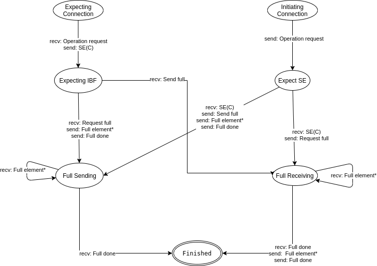